Page 2 of 3 FirstFirst 123 LastLast
Results 11 to 20 of 21

Thread: Vac Motor Wiring in the "Black Box"?

  1. #11
    Join Date
    Oct 2010
    Location
    Gainesville Florida
    Posts
    128

    Default

    Wow, I missed a lot while I was at the day job.

    Andrew, I do a lot of varied sized work. My plenum is 3/4" HDPE with 4-2x4 zones with the 4 in the "Y" direction. Each of those zones are fed with 2" pipe and a Valtera sliding valve from a 3" main. Each zone has 3 supply ports which will have individual "plugs" effectively giving me the option of 12 zones. The plenum grid is sized to accept Allstar gasketing. I have chosen to switch all four motors separately to give me complete control of how many and which motors to use.

    Jeff, I like the thermometer idea...hadn't thought of that. My vac box has separate chambers and check valves for each motor. I am using standard 2" PVC check valves which I split in half and mount to the individual vac ports on the side of the box. These will be "tee'd" into a 3" main with will be connected to a filter(next project) and then connected via flexible connection to the Shopbot 3" main.

    Michael, Good information. I meant ground but was in a hurry and had another voice in one ear and typed neutral.

    Ron, You hit my question on the head. I had thought about separate fusing but wasn't sure. I have a fairly good understanding of general shop wiring and common sense was telling me there was a problem going from #10 wire to smaller, and that running a 7 amp motor on a 30 amp breaker just seemed wrong. I think your idea of 8-10 amp fuses between the #10 wire and the individual switches confirms what I was thinking. I also purchased lighted switches so I will know when a fuse blows.

    I am planning an inline filter between the vac box and the Shopbot main line made out of a section of 10" PVC pipe, 3/4" sheet PVC, and a shop vac filter. I will post some pics of all this mess when I get a minute. Maybe I have over-thought all of this, but I like to try to be thorough (my wife calls it anal), and I remember Brady Watson telling others to make it your own way and learn what works for you. I appreciate all the information from all contributors to the Black Box sections of the forum and hope that maybe my ideas can contribute as well.

    Mark

  2. #12
    Join Date
    Jan 2004
    Location
    Fort Worth TX
    Posts
    445

    Default

    Several years ago I built a vacuum table using two vacuum motors. Each had a 'check valve', a flap that shut and prevented 'backflow' and separate switches. I also had a micro-switch mounted to a flat panel that opened when the panel sucked in.

    My 'zone control' was rubber balls I would set in ports of the areas I did not need. I could turn the vacuum motors on and pull down a piece of material. When there was enough vacuum to 'open' the micro-switch, one vacuum motor would switch off. It worked very well.

    Ron

  3. #13
    Join Date
    Nov 2014
    Location
    San Diego CA
    Posts
    107

    Default

    Quote Originally Posted by Mark Farris View Post
    Wow, I missed a lot while I was at the day job.

    Andrew, I do a lot of varied sized work. My plenum is 3/4" HDPE with 4-2x4 zones with the 4 in the "Y" direction. Each of those zones are fed with 2" pipe and a Valtera sliding valve from a 3" main. Each zone has 3 supply ports which will have individual "plugs" effectively giving me the option of 12 zones. The plenum grid is sized to accept Allstar gasketing. I have chosen to switch all four motors separately to give me complete control of how many and which motors to use.

    Jeff, I like the thermometer idea...hadn't thought of that. My vac box has separate chambers and check valves for each motor. I am using standard 2" PVC check valves which I split in half and mount to the individual vac ports on the side of the box. These will be "tee'd" into a 3" main with will be connected to a filter(next project) and then connected via flexible connection to the Shopbot 3" main.

    Michael, Good information. I meant ground but was in a hurry and had another voice in one ear and typed neutral.

    Ron, You hit my question on the head. I had thought about separate fusing but wasn't sure. I have a fairly good understanding of general shop wiring and common sense was telling me there was a problem going from #10 wire to smaller, and that running a 7 amp motor on a 30 amp breaker just seemed wrong. I think your idea of 8-10 amp fuses between the #10 wire and the individual switches confirms what I was thinking. I also purchased lighted switches so I will know when a fuse blows.

    I am planning an inline filter between the vac box and the Shopbot main line made out of a section of 10" PVC pipe, 3/4" sheet PVC, and a shop vac filter. I will post some pics of all this mess when I get a minute. Maybe I have over-thought all of this, but I like to try to be thorough (my wife calls it anal), and I remember Brady Watson telling others to make it your own way and learn what works for you. I appreciate all the information from all contributors to the Black Box sections of the forum and hope that maybe my ideas can contribute as well.

    Mark
    So Ron, and Mark, you are taking all of the motor's and using one wire from each motor and essentially connecting that to the 10 gauge wire? Then the other side/wire goes to the switches? Did anyone answer where ground comes into play here?

    I have a 220v 30A breaker coming from my shops panel, and it has a plug receptacle that I plug various machines into. Limited on breaker space so I have to plug/ unplug everything and can't have it permanently wired.

    Could I run a setup like this:
    Motors- 1 wire from each motor to #10 wire, other wire to: > lights > switches > fuses > #10 wire with plug > 220V receptacle > main shop panel. Running a ground from the motors all the way to the #10 wire with plug, which has already been connected from my main panels ground.
    PRS Alpha 96" X 48" w/ 12" Z
    4hp Spindle
    6" Indexer
    Aspire 8

  4. #14
    Join Date
    Oct 2010
    Location
    Gainesville Florida
    Posts
    128

    Default

    Justin,
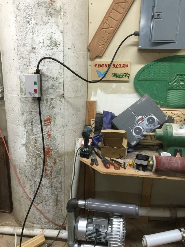
    No the motor wires are not connected to the #10 wire. I used #14 wire (black, red, and #12 green ground) from the motors to the switch box.

    At the switch box all #14 black and red wires are attached from each individual motor leads (1 black and 1 red each) to the outboard ends of a fuse holder. There is 10 amp ceramic fuse in each. The #10 wires from the inboard side of the fuse holder are connected to "lines". The green wire comes from " ground" to a ground post in the switch box then through and connected to 1 mounting bolt on each motor in series.

    The plastic that Andrew and I both used for our plenums is King Starboard. Don't forget to have an inline filter and (1) - 1/4" minimum hole per motor for cooling air.

    Please feel free to email me @ digifab12@gmail.com if you would like more info or pictures.

    Mark
    Attached Images Attached Images

  5. #15
    Join Date
    Oct 2010
    Location
    Gainesville Florida
    Posts
    128

    Default

    One more thing. There is no learning value to copying mine or anyone else's system. There is a world of information on this site that covers many variations of the original designs by Gary and Brady and no one system is right for everyone. You will find us all willing to share our ideas and experiences but it is up to you to build a system that is uniquely yours and tailored to how you work. If I were to build mine again there would be changes, but it works great for me and i wouldn't want to be without it again. Experiment, fail, and learn. It is what makes us.......well us.

    Mark

  6. #16
    Join Date
    Jan 2009
    Location
    Chapel Hill NC
    Posts
    41

    Default

    GM Mark
    did you have a chance to check the temp in your box? I am running about 162 F after 30 min and that's without a fan. the only time it goes passed that magic number is when there is too little air flow(10 or more "). when I am running at about 7-8" temp remains below 162.

    Larry

  7. #17
    Join Date
    Nov 2014
    Location
    San Diego CA
    Posts
    107

    Default

    Thanks Mark, that makes sense. So you have the fuses before the switches? I got 30A toggle switches from HD instead of going with any kind of relays. I am basically going to wire nut a #10 wire and 4, #16 wires together for each line of the incoming power inside the box, then run those #16 wires to the switches/ fuses (whichever is better to be first). I am going to have 4 switches to control the motors independently, each motor with their own check valves held down by gravity and only opened when the motor is actuated. Before anyone chews me out, I am sure the system will probably need all four motors to cut full sheets with lots of parts. I am only doing this because its fun 1, and 2, I am kind of a freak about symmetry and do not like to run 2 motors most of the time, etc.
    PRS Alpha 96" X 48" w/ 12" Z
    4hp Spindle
    6" Indexer
    Aspire 8

  8. #18
    Join Date
    Apr 2007
    Location
    Marquette, MI
    Posts
    3,388

    Default

    Guys...
    Don't forget that when switching or fusing 220V lines, you must put a fuse on each line (8 singles or 4 doubles) and switches must be double pole as both hot lines must be disconnected. You must also ground all of the vac motor metal housings. There is a ground lug boss provided for this purpose.

    There are volumes of online documents that give some basics to amateur electricians. This is slightly beyond the basics, read up before you kill yourself or a friend.
    Last edited by Gary Campbell; 05-30-2015 at 01:45 PM.
    Gary Campbell
    GCnC Control
    GCnC411(at)gmail(dot)com
    Servo Controller Upgrades
    http://www.youtube.com/user/Islaww1


    "We can not solve our problems with the same level of thinking that created them"
    Albert Einstein


  9. #19
    Join Date
    Sep 2006
    Location
    cnc routing, portland or
    Posts
    3,633

    Default

    and when you get tired of these motors yo can go this way. I hated spending the money but i wanted the reliability and the quiet.

  10. #20
    Join Date
    Oct 2010
    Location
    Gainesville Florida
    Posts
    128

    Default

    Justin,
    I am no electrical genius but I believe the purpose of the fuse is to separate and protect the lower amperage components from the higher. I am using a 30A 220V breaker feeding my setup into the switch box with #10 wire. The #10 wire runs to the inboard side of all 8 fuse holders (thanks to Gary for bringing that up), the #14 wire comes off the outboard side of the fuse holders to the double pole single throw lighted switches from McMaster-Carr, then to the motors. #14 wire is not rated to carry 30A and is protected, as are the motors, with a 10A fuse on each leg of the 220V power supply. The ground wire basically goes all the way from the ground source to the motor casings and is daisy chained between them.

    Larry, haven't had time to check the temps yet, been too busy running it. LOL I need to make that a priority.

    Mark

Similar Threads

  1. Selling: Shopbot 2016 PRS Alpha 48"x48"-12"
    By rohit in forum For Sale/Wanted - ShopBot-related items only
    Replies: 4
    Last Post: 08-11-2016, 05:01 PM
  2. PRTALPHA 120 X 60 X 6, w 3HP Colombo, 6" Index Head w 18"x18" x10' alcove in table
    By PVWoodworks in forum For Sale/Wanted - ShopBot-related items only
    Replies: 0
    Last Post: 08-12-2015, 07:09 PM
  3. How to suspend the 4" dust hose over 96" x 60" shopbot?
    By digitalrust in forum ShopBotter Message Board
    Replies: 7
    Last Post: 04-06-2015, 05:30 PM
  4. Breaking Bits After an "S" stop and "R" resume
    By cabindoors in forum Troubleshooting
    Replies: 19
    Last Post: 12-17-2010, 05:34 PM
  5. Getting "Missing Comm" or "Communitation Error"
    By dengler in forum ShopBotter Message Board
    Replies: 1
    Last Post: 07-02-2010, 04:22 PM

Posting Permissions

  • You may not post new threads
  • You may not post replies
  • You may not post attachments
  • You may not edit your posts
  •