Hello Shopbot Friends. I had to break this into 3 posts, with 4 pictures being the limit for any one post.
Part 1
Last September, in a quest to improve the rigidity of my X Gantry, I replaced the factory supplied aluminum struts with rectangular steel tubing (1.5” x 2.5”).
With the X gantry in position on by PRT alpha (60 x 144), I measured the distance between the two “motor carriers”, carefully cut the steel tubing to length, removed the aluminum struts, clamped the steel tubing in place, and took great care to make sure that the rectangular steel tubing was exactly perpendicular to the 3” square steel tubing of the X1 “motor carrier”.
After welding the gantry together, and then mounting the Y rails to the X gantry,(again taking great pains to make sure both Y rails were perpendicular to the X1 motor carrier’s 3” steel tubing, I realized that I should have made sure that the Y rails were perpendicular to the X rails. But of course they would be,,, why wouldn’t they be??????
Horror of horrors, I found in fact that at the far end of the Y rails (relative to the X1 motor carrier) was out of square by about 1 inch,,,,,,,, or enough that no amount of egging of holes, or re-locating the tapped holes that attach the Y rails to the X gantry rectangular tubing, could make the Y rails be perpendicular to the X rails. How could this be, when in fact the Y rails were perpendicular to the 3” square tubing of the X1 motor carrier?
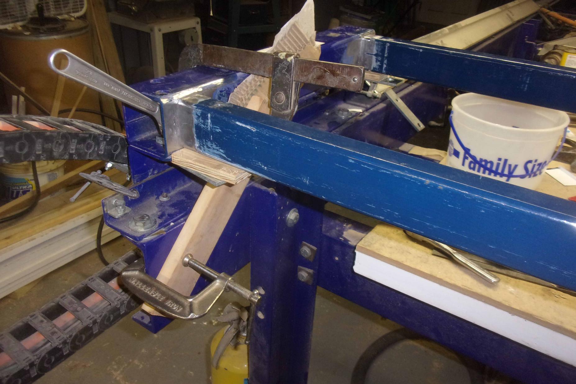
If you look at picture A, and you will see that the “Motor carriers” at both ends of the X gantry are each made of two pieces of steel, the “long angle bracket” and the “3” square steel tubing”. As it turned out, the long angle bracket and the 3” square steel tubing were NOT aligned as I thought they were. I “ASSumed” that the long faces of these two parts would have been co-planer in both the long dimension (X axis) and in the short dimension (Z axis). And they were not co-planer in either dimension…. (This is perhaps hard to explain/understand,,, but when looking at this picture (that was taken after the fix was made), the top of the long angle bracket was tipped back slightly, and one end of the long angle bracket was not even with the same end of the 3” square steel tubing.
This out of whack alignment of the parts of the “motor carriers” was not a problem with the original aluminum struts, because with the strut bolts loose, it was easy to just slide everything around until the Y rails were perpendicular to the X rails, then the bolts would be tightened to lock everything in place……. Easy……
So, to fix my welded, out of alignment X gantry, I had to grind off all of the welding to separate the motor carriers from the rectangular tubing. Then, with LOTS of grinding, and using big wedges, a Sawz-all, a big hammer and a grinder, I was able to separate the long angle brackets from the 3” square steel tubing. (Picture B). And I had to flip the 1.5”x 2.5” rectangular steel tubes over, so that I would move all of my drilled and tapped holes onto the bottoms, where no one would see my mistakes...
Then I wanted to do a dry mock-up, to make sure everything would be OK BEFORE welding the X gantry back together a second time……. So I placed long threaded rods inside of both the rectangular tubes, which then allowed me to bolt the X motor carriers to the rectangular steel tubing. (Picture C). And I bolted the long angle brackets to the 3” square steel tubes. Because of the precision cutting of my rectangular steel tubing, I was able to square and tighten the basic gantry assembly itself. (Picture D).


 Reply With Quote


